What’s our goal?
To connect a MAX7219 based LED Matrix module to an ATtiny85 microcontroller and control the LEDs.
Doesn’t sound very complicated, right?
The Hardware
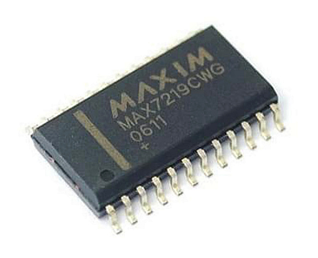
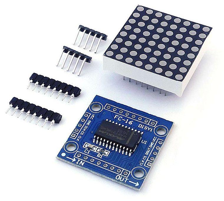
The MAX7219 controller manufactured by Maxim Integrated is a compact, serial input/output common-cathode display driver that could interface microcontrollers to 64 individual LEDs, 7-segment numeric LED displays of up to 8 digits, bar-graph displays, etc. Included on-chip are a BCD code-B decoder, multiplex scan circuitry, segment and digit drivers, and an 8×8 static RAM that stores each digit.
The MAX7219 modules are very convenient to use with microcontrollers such as ATtiny85, or, in our case with the Tinusaur Boards.
They have an input bus on one side and an output bus on the other. This allows you to daisy chain 2, 3, and more modules, i.e. one after another, to create more complicated setups.
The modules that we are using are capable of connecting in a chain using 5 small jumpers. See the picture below.
Pinout and Signals
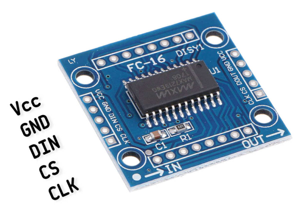
MAX7219 module that we are going to use has input 5 pins:
- VCC – power (+)
- GND – ground (-)
- DIN – Data input
- CS – Chip select
- CLK – Clock
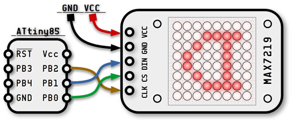
That means that we will need 3 ATtiny85 pins to control the module. Those will be:
- PB0 connected to CS
- PB1 connected to DIN
- PB2 connected to CLK
Why did we choose those ATtiny85 pins to connect to those MAX7219?
If we look at the ATtiny85 pinout (picture below) we will notice the following:
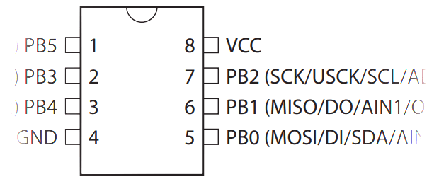
- The PB2 pin is often used to output a clock signal ( SCK / USCK / SCL ), so it will be a good idea to use it for the same thing in our setup.
- The PB1 pin is commonly used to output data ( MISO / DO ) so we could use it the same way.
- The PB0 pin is often used for data input. We don’t need to input data so we will use it for the CS signal.
These are all the signals that we need to connect to the MAX7219 module.
How to Connect?
For the MAX7219 module to work we need 5 connections in total: 3 for the DIN/CS/CLK signals and 2 for the VCC/GND power lines.
You can use I/O ports different from the ones specified here, but you will have to make changes in the code examples in this article.
The Communication Protocol
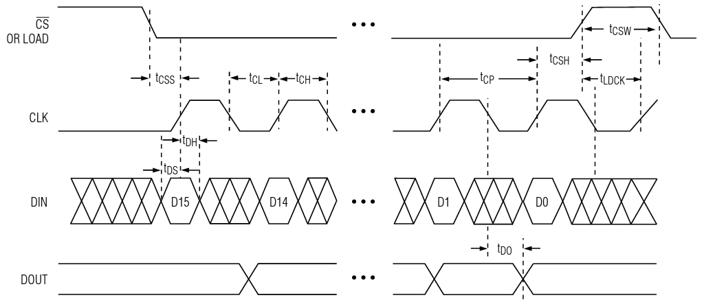
Communicating with the MAX7219 is relatively easy – it uses a simple synchronous protocol which means that for every data bit we send we also send a clock cycle that signifies the presence of that data bit. In other words, we send 2 parallel sequences to bits – one for the clock and another one for the data.
This is how it works:
In a single module setup: We put the CS signal to low and we start the transmission of the data bits. This is a sequence of putting CLK to low, followed by putting DIN to low/high (depending on the data), followed by putting CLK to high. In the end, we put CS to high to mark the end of the transmission.
To control the module we send commands that consist of 2 bytes of data which means that we must send the 2 bytes of data before we bring the CS signal back to high.
The Software
The way the MAX7219 modules work is this:
- We send a sequence of bytes to the MAX7219 internal registers.
- MAX7219 interprets the data.
- MAX7219 controls the LEDs in the matrix (or matrices).
That also means that we don’t have to circle through the array of LEDs all the time in order to light them up – the MAX7219 controller takes care of that. It could also manage the intensity of the LEDs.
So, to use the MAX7219 modules in a convenient way we need a library of functions to serve that purpose.
First, we need some basic functions in order to write bytes to the various MAX7219 registers.
Let’s define our pins
#define MAX7219_CS		PB0	// CS,	pin 4 on the MAX7219 Board
#define MAX7219_DIN		PB1	// DIN,	pin 3 on the MAX7219 Board
#define MAX7219_CLK		PB2	// CLK,	pin 5 on the MAX7219 Board
For convenience, we will create 6 macros that will put those 3 pins at high and low.
#define MAX7219_CS_HI()		PORTB |= (1 << MAX7219_CS)
#define MAX7219_CS_LO() 	PORTB &= ~(1 << MAX7219_CS)
#define MAX7219_CLK_HI()	PORTB |= (1 << MAX7219_CLK)
#define MAX7219_CLK_LO()	PORTB &= ~(1 << MAX7219_CLK)
#define MAX7219_DIN_HI()	PORTB |= (1 << MAX7219_DIN)
#define MAX7219_DIN_LO()	PORTB &= ~(1 << MAX7219_DIN)
The function that writes one byte to the controller would look like this:
void max7219_byte(uint8_t data) {
	for(uint8_t i = 8; i >= 1; i--) {
		MAX7219_CLK_LO();		// Set CLK to LOW
		if (data & 0x80)		// Mask the MSB of the data
			MAX7219_DIN_HI();	// Set DIN to HIGH
		else
			MAX7219_DIN_LO();	// Set DIN to LOW
		MAX7219_CLK_HI();		// Set CLK to HIGH
		data <<= 1;				// Shift to the left
	}
}
Now that we can send bytes to the MAX7219 we can start sending commands. This is done by sending 2 bytes – 1st for the address of the internal register and the 2nd for the data we’d like to send.
Sending commands, or words is basically sending 2 consecutive bytes. The function implementing that is very simple.
void max7219_word(uint8_t address, uint8_t data) {
	MAX7219_CS_LO();		// Set CS to LOW
	max7219_byte(address);	// Sending the address
	max7219_byte(data);		// Sending the data
	MAX7219_CS_HI();		// Set CS to HIGH
	MAX7219_CLK_LO();		// Set CLK to LOW
}
It is important to note here the source code line where we bring the CS signal back to HIGH – this marks the end of the sequence – in this case, the end of the command. A similar technique is used when controlling multiple matrices connected in a chain.
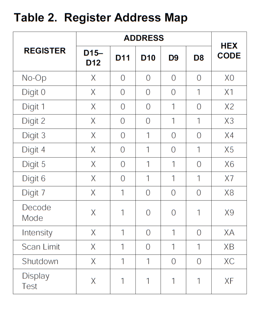
Let’s now take a look at the internal MAX7219 registers. There are more than a dozen registers in the controller.
The next step, before we start turning on and off the LEDs, is to initialize the MAX7219 controller. This is done by writing specific values to certain registers. For convenience, while coding it, we could put the initialization sequence in an array.
const uint8_t max7219_initseq[] PROGMEM = {
	0x09, 0x00,	// Decode-Mode Register, 00 = No decode
	0x0a, 0x01,	// Intensity Register, 0x00 .. 0x0f
	0x0b, 0x07,	// Scan-Limit Register, 0x07 to show all lines
	0x0c, 0x01,	// Shutdown Register, 0x01 = Normal Operation
	0x0f, 0x00,	// Display-Test Register, 0x01, 0x00 = Normal
};
Note the use of const and PROGMEM. This will ensure that those values are put in the Flash memory and read directly from there while our program runs. For the same reason, we will have to use the pgm_read_byte() function to access the array values.
This initialization function sends the 5 commands to the MAX7219 controller.
void max7219_init(void) {
	DDRB |= (1 << MAX7219_CLK);	// Set CLK port as output
	DDRB |= (1 << MAX7219_CS);	// Set CS port as output
	DDRB |= (1 << MAX7219_DIN);	// Set DIN port as output
	for (uint8_t i = 0; i < sizeof (max7219_initseq);) {
		uint8_t opcode = pgm_read_byte(&max7219_initseq[i++]);
		uint8_t opdata = pgm_read_byte(&max7219_initseq[i++]);
		max7219_word(opcode, opdata);
	}
}
The next step – lighting up a row of LEDs.
How it works
At this point, It is important to understand how addressing the individual pixels with MAX7219 works and what happens when we send the data to it.
When we write one byte of data to any of the 8 digits’ registers (Digit 0 through Digit 7) the bits of that byte light on or of one LED on the matrix.
The pixels are filled out left-to-right, bottom-to-top.
Pixel on and off
This is very simple – we just write one command where the 1st byte is the address (from 1 to 8) and the 2nd byte is the 8 bits data representing the 8 LEDs in the row. We also need to check, just in case, if the address is within the boundaries.
void max7219_row(uint8_t address, uint8_t data) {
	if (address >= 1 && address <= 8) max7219_word(address, data);
}
It is important to note that this will work for 1 matrix only. If we connect more matrices in a chain, they will all show the same data. The reason for that is that after sending the command we bring the CS signal back to HIGH which causes all the MAX7219 controllers in the chain to latch and show whatever the last command was.
To control multiple matrices we need a bit more complex procedure of sending out the data. That will be the subject of another article.
Testing
This is a simple testing program that lights up a LED on the first row (r=1) on the right-most position, then moves the lit-up LED on the left (by shifting the bits to the left) until it reaches the left-most position. Then it does the same on the next row up (r=2) until it reaches the top (r=8).
for (uint8_t r = 1; r <= 8; r++) {
	uint8_t d = 1;
	for (uint8_t i = 9; i > 0; i--) {
		max7219_row(r, d);
		d = d << 1;
		_delay_ms(100);
	}
}
Note that the inner loop executes 9 times, so the last value written in the row will be 0 – all LEDs off.
This testing code doesn’t do much but it demonstrates how to communicate with the MAX7219 controller.
The MAX7219tiny Library
We wrote a simple library called MAX7219tiny, based on the code above, that could be used to work with MAX7219 modules. It actually does more than what was shown in this article.
- MAX7219tiny Library Page: https://tinusaur.com/libraries/max7219tiny/
- MAX7219tiny Source Code: https://gitlab.com/tinusaur/max7219tiny
- MAX7219tiny GitHub mirror at: https://github.com/tinusaur/max7219tiny
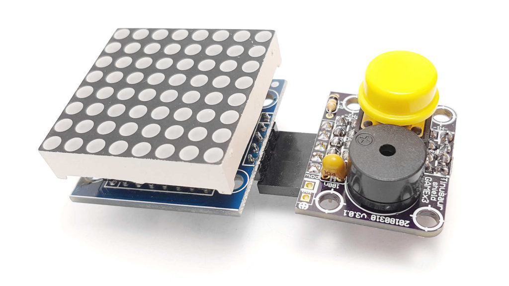
The Tinusaur Shield GAMEx3
If you already have a Tinusaur Board we have the Shield GAMEx3 (Generation-4) for it. It is a great addition to our boards and gives you a convenient way of connecting the MAX7219 modules to your microcontroller projects.
MORE INFORMATION IS COMING SOON
The Gametinu Project
The Gametinu is a small game platform that you could build yourself using the Tinusaur Shield GAMEx3 and a few more parts and tools.
MORE INFORMATION IS COMING SOON
Final Words
References
MAX7219 specification and datasheet:
- http://www.maximintegrated.com/…/MAX7219.html
- http://datasheets.maximintegrated.com/en/ds/MAX7219-MAX7221.pdf
Older Articles
This article is a rewritten version of 2 older articles:
- Interfacing a MAX7219 Driven LED Matrix with ATtiny85 (2019)
- MAX7219 driver for LED Matrix 8×8 (2014)
Comments and Suggestions
Please, leave a comment or make a suggestion below this blog post: https://tinusaur.com/2022/01/16/how-to-connect-max7219-attiny85-8×8-led-matrix/.