In our previous tutorial, we discussed how to create an interface between the ATtiny85 microcontroller and MAX7219 controller for LED matrices. We created 4 basic functions: max7219_byte, max7219_word, max7219_init, and max7219_row and they work great with a single 8×8 LED matrix.
Let’s take a step further and connect more LED 8×8 matrices.
What’s our goal?
Let’s now see how we could work with multiple matrices connected in a chain, light up some LEDs and use a memory buffer to save the current state of the LEDs.
The Hardware
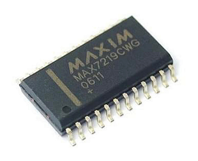
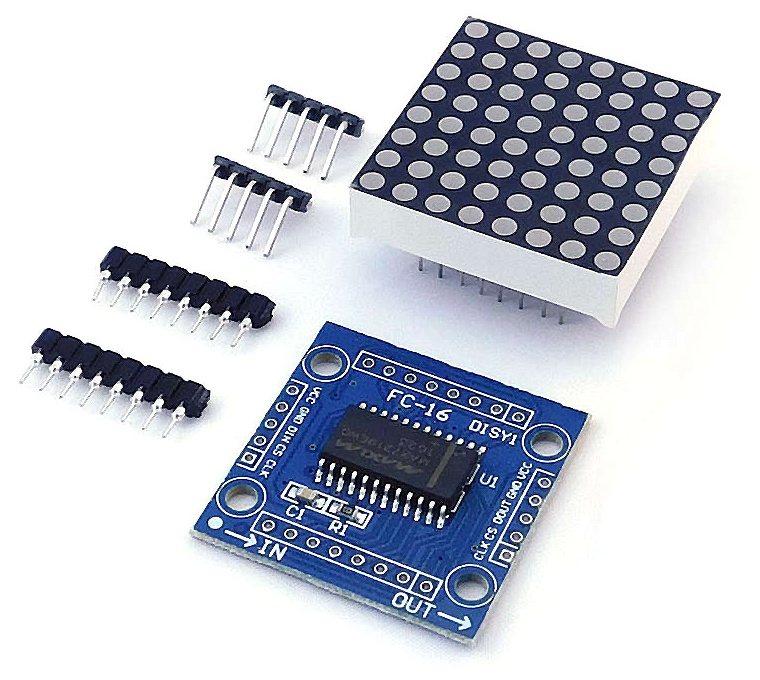
The MAX7219 controller manufactured by Maxim Integrated is a compact, serial input/output common-cathode display driver that could interface microcontrollers to 64 individual LEDs, 7-segment numeric LED displays of up to 8 digits, bar-graph displays, etc. Included on-chip are: a BCD code-B decoder, multiplex scan circuitry, segment and digit drivers and an 8×8 static RAM that stores each digit.
The MAX7219 modules are very convenient to use with microcontrollers such as ATtiny85, or, in our case with the Tinusaur Boards.
For pinout and signals check our previous tutorial about creating an interface between ATtiny85 microcontroller and MAX7219.
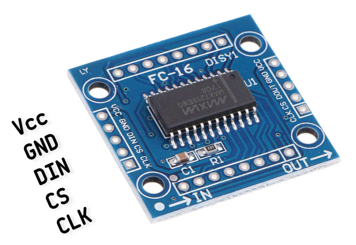
How to Connect a Single MAX7219 Module?
For the MAX7219 module to work we need 5 connections in total: 3 for the DIN/CS/CLK signals and 2 for the VCC/GND power lines.
You can use I/O ports different from the ones specified here, but you will have to make changes in the code examples in this article.
For details about the Communication Protocol between the ATtny85 and the MAX7219 controller check our previous tutorial about creating an interface between ATtiny85 microcontroller and MAX7219.
How to Connect Multiple MAX7219 Modules?
The MAX7219 modules have an input bus on one side and an output bus on the other. This allows you to daisy chain 2, 3, and more modules, i.e. one after another, to create more complicated setups.
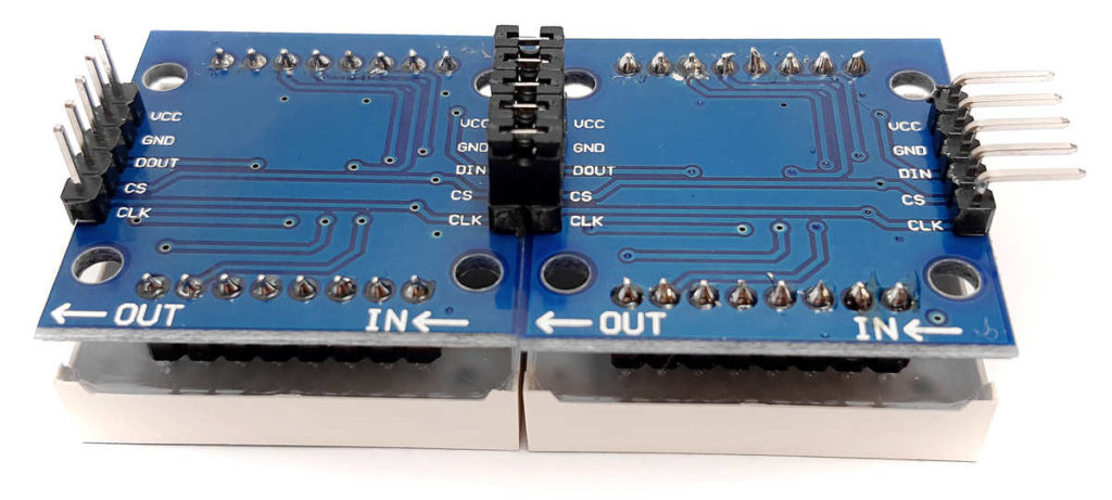
The modules that we are using could be connected in a chain using 5 small jumpers.
How do Multiple Modules Work?
In a single module setup we put the CS signal to low and we start the transmission of the data bits. This is a sequence of putting CLK to low, followed by putting DIN to low/high (depending on the data), followed by putting CLK to high. In the end, we put CS to high to mark the end of the transmission.
To control the module we send commands that consist of 2 bytes of data which means that we must send the 2 bytes of data before we bring the CS signal back to high.
When we use multiple MAX7219 modules connected in a chain, the first module will pass all the data over to the next module without any change, but will “remember” only the last command (the 2 bytes data) sent to it.
So, if we have 2 modules, the first command goes to the first module. When we send the second command it will go to the first module, but the first module will pass the (previous) first command to the second module.
For this, to work we must keep the CS signal low until we send all the commands for all the modules in the chain. In the end, as usual, we bring the CS signal back to high.
Buffering
As we are going to use multiple LED 8×8 matrices, it is a good idea to make things a bit more advanced and use a memory buffer to keep the status of the LEDs. That means we are going to write only in the memory buffer (RAM) what we want to display and will output the buffer from time to time.
Here are awesome advantages of doing it this way:
- We could do some visual effects such as scrolling left and right, or flashing. This cannot be (easily) done without a buffer.
- We could use a timer that will output the buffer as often as needed and focus the rest of the code on the actual work that needs to be done.
There are of course some drawbacks: If we have too many matrices there may be not enough memory for the buffer. Let’s do some calculations: if we have 50 matrices and we need 8 bytes of buffer memory for each matrix that means it will “eat” 400 bytes of our RAM which is almost 80% of it.
Buffering is not always possible especially when there are too many pixels to handle. This is the case with our SSD1306xLED library. It controls OLED display with up to 128×64 array of pixels. That is 8192 pixels and they will require 1024 bytes of buffer but we have only 512 bytes on the ATtiny85.
Transposition
In our previous tutorial about MAX7219, we saw how the controller fills out the matrix: left-to-right & bottom-to-top.
This is not always convenient, especially when we want to output characters and scroll them left or right. Filling out the screen top-to-bottom, left-to-right will be more convenient.
Transposition of the coordinates
Since we are using a buffer we could easily transpose the coordinates and fill out the screen top-to-bottom, left-to-right. That requires a bit more complicated addressing arithmetics and some bitwise operations but once done it will do everything for us.
The Software
Let’s go through the data and the code we need to write or change (from the previous tutorial) to work with multiple matrices.
The Buffer
We need to reserve a segment of the RAM for the buffer. That will be 8 bytes for each matrix we’d like to have on the chain.
#define MAX7219_SEG_NUM 2 // The number of the segments.
#define MAX7219_BUFFER_SIZE MAX7219_SEG_NUM * 8 // The size of the buffer
uint8_t max7219_buffer[MAX7219_BUFFER_SIZE];
It is always a good practice to use definitions instead of just numbers.
Sending Commands
Next, we need to improve the init function to handle multiple matrices.
But before that we need to make changes in the function that sends commands to the MAX7219 controller – the max7219_word() function. What we have to do is add another parameter uint8_t num to specify how many matrices we have on the chain. Then, as discussed above, we bring the CS signal to low and start sending the command but this time num number times. Then we bring the CS signal back to high.
Initialization
Next, let’s update the max7219_init() function to use the new version of the max7219_word(). Another change we should do is to save the number of the matrices num to the global __max7219_num variable, the address pointer of the buffer to the global __max7219_buffer variable, and the size of the buffer to the global __max7219_buffer_size variable.
There is a reason why we keep both the number of the matrices and the buffer size separately. Note that the buffer size might not always be the number of matrices multiplied by 8 – it could be larger than that. A good example of such a scenario would be if we want to have an extra space in the buffer for a character that will scroll into the display from the right.
We are now ready to output the buffer.
Buffer Output
This is the max7219b_out() function.
The buffer output function should do 2 things: (1) output the data from the memory buffer; (2) transpose the coordinates as described above.
Output the Data
This is trivial – it is not very different from the max7219_word() function. The difficult part is how to change the order of the output commands to transpose the coordinates.
Transpose the Coordinates
The idea is simple and goes like this:
- We go by row, i.e. output the 1st row for all of the matrices in the chain, then we go with the 2nd row and so on, until we reach the 8th row. That is why we start with a for() loop for the 8 rows.
- We put the CS signal to low every time we start working on a row and back to high when we finish a row.
- We go through each segment in the buffer (for each matrix) and retrieve each column from the buffer.
- For the current column, we check the current bit if it is 0 or 1. The current bit is the one we want to output currently. For row 1 this is the left-most (the 8th bit), for the 2 row it is the next to the right (the 7th bit) and so on.
- Whether the bit is 0 or 1 we output that to the DIN signal. We use a bitmask to do the but check.
- The bit mask should be moved to the right on each row.
Sample implementation:
void max7219b_out(void) {
	uint8_t bit_mask = 0x80;
	for (uint8_t row = 1; row <= 8; row++) {
		uint8_t buffer_seg = __max7219_buffer_size;
		MAX7219_CS_LO();
		while (buffer_seg != 0) {
			max7219_byte(row);
			for (uint8_t index = 8; index != 0; index--) {
				uint8_t col = __max7219_buffer[buffer_seg + index - 9];
				MAX7219_CLK_LO();
				if (col & bit_mask)
					MAX7219_DIN_HI();
				else
					MAX7219_DIN_LO();
				MAX7219_CLK_HI();
			}
			buffer_seg -= 8;
		}
		MAX7219_CS_HI();
		MAX7219_CLK_LO();
		bit_mask >>= 1;
	}
}
We should call this function from time to time to output the buffer.
That could: (1) every time we make a change in the buffer; (2) on regular intervals using a hardware timer (ex.: 20 times per second); (3) any other criteria, could be a combination of the other two.
Pixels
Let’s create a few basic functions to work with the buffer
Set and Clear a Pixel
This is very simple, we just use bitwise operations to change the bit.
void max7219b_set(uint8_t x, uint8_t y) {
	if (x < __max7219_buffer_size) __max7219_buffer[x] |= (1 << y);
}

void max7219b_clr(uint8_t x, uint8_t y) {
	if (x < __max7219_buffer_size) __max7219_buffer[x] &= ~(1 << y);
}
Set and Get a Column
We could also have a function that sets an entire column in the buffer.
void max7219b_col(uint8_t x, uint8_t data) {
	if (x < __max7219_buffer_size) __max7219_buffer[x] = data;
}
We may also need to read the contents of a column.
uint8_t max7219b_get(uint8_t x) {
	return __max7219_buffer[x];
}
Scrolling
Let’s move all the bytes to the left.
void max7219b_left(void) {
	memcpy(__max7219_buffer, __max7219_buffer + 1, __max7219_buffer_size - 1);
}
We are using the memcpy() function to do that.
Testing
This is a simple testing program that will light up a pixel and will “move” it across the display.
#define MAX7219_SEG_NUM 2 // The number of the segments. Change this for multiple matrices.
#define MAX7219_BUFFER_SIZE	MAX7219_SEG_NUM * 8 // The size of the buffer
uint8_t max7219_buffer[MAX7219_BUFFER_SIZE];
int main(void) {
	max7219b_init(MAX7219_SEG_NUM, max7219_buffer, MAX7219_BUFFER_SIZE);
	for (;;) {
		for (uint8_t x = 0; x <= MAX7219_SEG_NUM * 8 - 1; x++) {
			for (int8_t y = 0; y <= 7; y++) {
				max7219b_set(x, y);		// Set the pixel
				max7219b_out();			// Output the buffer.
				_delay_ms(20);
				max7219b_clr(x, y);		// Clear the pixel
			}
		}
	}
	return 0; // Return the mandatory result value.
}
[VIDEO] testing program working TO-DO!
The MAX7219tiny Library
We wrote a simple library called MAX7219tiny (based on the code above) that could be used to work with MAX7219 modules. It actually does more than what was shown in this article.
- MAX7219tiny Library Page: https://tinusaur.com/libraries/max7219tiny/
- MAX7219tiny Source Code: https://gitlab.com/tinusaur/max7219tiny
- MAX7219tiny GitHub mirror at: https://github.com/tinusaur/max7219tiny
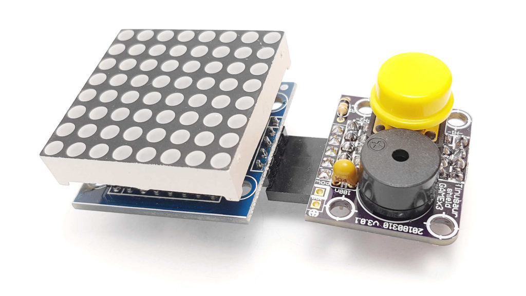
The Tinusaur Shield GAMEx3
If you already have a Tinusaur Board we have the Shield GAMEx3 (Generation-4) for it. It is a great addition to our boards and gives you a convenient way of connecting the MAX7219 modules to your microcontroller projects.
MORE INFORMATION IS COMING SOON
The Gametinu Project
The Gametinu is a small game platform that you could build yourself using the Tinusaur Shield GAMEx3 and a few more parts and tools.
MORE INFORMATION IS COMING SOON
Final Words
References
MAX7219 specification and datasheet:
- http://www.maximintegrated.com/…/MAX7219.html
- http://datasheets.maximintegrated.com/en/ds/MAX7219-MAX7221.pdf
Older Articles
This article is a rewritten version of 2 older articles:
- Interfacing a MAX7219 Driven LED Matrix with ATtiny85 (2019)
- MAX7219 driver for LED Matrix 8×8 (2014)
Comments and Suggestions
Please, leave a comment or make a suggestion below this blog post: https://tinusaur.com/2022/01/16/how-to-connect-max7219-attiny85-8×8-led-matrix/.